2007 - Volume #31, Issue #4, Page #16
[ Sample Stories From This Issue | List of All Stories In This Issue | Print this story
| Read this issue]
Big Square Bale Loader "Has Tremendous Capacity"
 |
 |

"My boss is a real visionary type of guy," says Shaum. "He looked at an existing loader, but it wouldn't work for what we were doing. We drew up what we wanted and had an engineer draw up some basic plans. We revised and built from there."
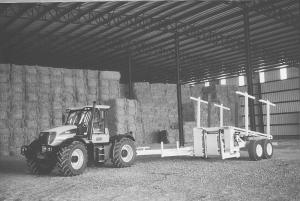
What Shaum built was a loading wagon large enough to hold 12 large 3 by 4-ft. bales favored by J&J for their export business. It also could handle eight 4 by 4-ft. bales or eighteen 3 by 3-ft. bales.
The wagon itself is double framed with the lower frame serving as a mount for the walking beam mounted double axle. It also serves as a base for a working table with two pivot points, one front and one back. The working table consists of two sections with the larger section riding on the lower frame at a slightly descending angle from front to back. The front section is designed to hold two 3 by 4-ft. bales stacked. It hangs over the forward pivot point.
The second section holds five sets of stacked bale pairs. It extends over the rear pivot point on the lower frame.
Two pairs of arms extend out from the front end of the frame and to the side of the hanging front section. The shorter arms are about 3 1/2 ft. long while the longer arms are about 7 1/2 ft. When the wagon is empty, two uprights stand at the front of the rear section of the table, just behind the front section. The uprights are a rolling rack and made from two forklift forks. Two upright stakes are mounted to either side of the rear section of the working table.
Hydraulic cylinders control the entire loader. Electro-hydraulic valves provide rapid activation of cylinders. The entire process requires 14 cylinders from 3-in. with 1 1/2-in. rod on the front section of the working table to 4-in. cylinders with 2-in. rod and 40-in. reach to lift the table for dumping. Cylinders were bought stock and modified as needed with new ends or shorter rods on site in the farm's shop.
"It got to the point where we needed a hydraulic consultant to help us," says Shaum. "We can run the unit either open center or closed for quicker response, depending on the component. We needed a flow rate of at least 30 gpm to operate."
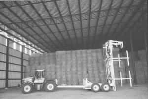
To load the unit, the operator drives up to a large bale and picks it up with the short arms. He then drives up to a second bale, dropping the first one immediately in front of the second bale. He then grabs both bales, one with each set of arms, and raises them off of the ground and into the air. The front working table section rises up and under the two bales until it is in line with the rear section. A chain with a paddle is activated to come up and push the bales back onto the second section. The hydraulic pressure on the chain is greater than the relief valve on the rolling rack and the bales move down the table. As they do so, the front table section drops back down, as do the arms.
As the process is repeated, the working table fills. The last two bales remain on the front section as the loader heads for the stack. At the same time, the two pairs of side uprights are brought in to help hold the bales stable and to square up the stack.
Once at the stack, the operator backs into place and the entire working table raises up from the front and pivots over the end of the lower frame, to an angle of more than 90¦. This helps the bales slide off the rolling rack as the operator pulls away.
Lifting and moving heavy bales at high speed (up to 150 bales per hour) across the field requires heavy-duty components. The main frame is built from 3/8-in., 4 by 10-in. steel tubing, and the two sections of the working table are made with 3/8-in., 4 by 8-in. steel tubing. The arms are made of 3/8-in., 4 by 4-in. tubing with 2-ft. lengths of heavy wall steel pipe at the ends of the arms.
The rolling rack is moved back and forth by a hydraulic cylinder with a 72-in. reach connected to a cable. The cable runs from the cylinder over a pulley to rack. When cylinder arm moves 1 ft., the rack moves 2 ft.
The walking beam axles are made from 1/2-in. plate and pivot at their centers. Stubs extend outward from the walking beam where they're bolted into short sections of drawn-over-mantle (DOM) steel tubing. The tubing is welded in the walking beam for easy spindle replacement should one break. The entire bale loader weighs about 15,000 lbs.
The tongue is made from high tensile plated, 1/2-in. thick, 6 by 8-in. rectangular tubing. The heavy-duty tongue allows the operator to position the stacker as he backs up to the stack to unload. It also allows him to quickly move into transport mode.
All hoses and cables run through the tongue to a control panel in the tractor cab that was designed to handle the multitude of levers and switches. Shaum hasn't totaled the cost of building the loader. Hydraulic components alone total more than $5,500.
Contact: FARM SHOW Followup, Glenn Shaum, 28485 Peoria Rd., Halsey, Ore. 97348 (ph 541 369-3538; ggshaum3@gmail.com).
Click here to download page story appeared in.

Click here to read entire issue
To read the rest of this story, download this issue below or click here to register with your account number.