2005 - Volume #29, Issue #2, Page #10
[ Sample Stories From This Issue | List of All Stories In This Issue | Print this story
| Read this issue]
Big Sprayer Built For Muddy Fields
 |
 |
 |
 |
 |
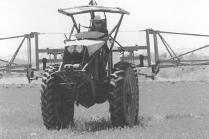
"It has tremendous pull in the mud," he says. "We had a spot where water flowed through a plowed area after a heavy rain. I drove it in, and it sank to the axle hubs. It groaned a little, but it climbed right back out."
To get that kind of pull, Ellsworth built his rig lightweight and put big tractor tires on it with articulated steering. The self-leveling boom hangs from a pivot point like a pendulum.
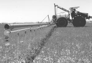
The 4-cyl. motor and transmission came out of a Toyota Corona car. The operator seat and controls are mounted on the front end. The 325-gal. tank and 100-ft. boom mount at the rear. Axles and differentials were reclaimed from two cars with the same gear ratio, while four 38-in. high Farmall M wheels were adapted to fit the car axles.
Ellsworth used old chains and sprockets to build an 8-to-1 gear reduction unit to slow the drive shaft. A chain transfers power to a sprocket welded to the front differential, and a telescoping driveline transfers power from the front to the rear end differential.
"The telescoping drive line minimizes the effect of articulation by splitting the angle at each differential," explains Ellsworth.
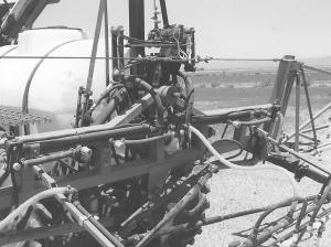
The two yokes flex at the hinge point, a unique joint Ellsworth designed that allows front and rear yokes to pivot independently of each other. A framework is built around it for the two hydraulic cylinders that turn the power unit.
"The key to articulation working is for the hinge point to be exactly halfway between the two axles," says Ellsworth. "If it is, you can take two axles off the same model car and turn one around and you get 4-WD."
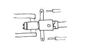
The hinge bracket is similar to a clevis-type tool bar hitch. A center beam welded from two channel irons extends from the rear frame forward to fit between the jaws of the clevis-type bracket. Two bushing supports in the beam hold a bushing bracket. A bolt extending through the jaws of the bracket and the bushing bracket forms the pivot or articulation point of the rig.
An 18-in. long by 1-in. thick by 2-in. wide steering bar is welded to the back of the hinge bracket and forward of the articulation point. The ends of the bar extend about 7 in. out to either side of the bracket. Hydraulic cylinders mounted to the axle of the rear unit and about a foot to either side of the bracket extend out to connect to the ends of the steering bar.
A steel tube machined down from the arm of a heavy-duty hydraulic cylinder is welded to the front of the bracket and extends forward and through a sleeve machined out of the same cylinder. It is this sleeve that is welded to the frame of the front end of the power unit. An end cap bolted to the inner tube extends over the edges of the sleeve and holds the front and rear structures together.
When a hydraulic cylinder is extended, the bracket is forced to pivot, causing the unit to turn left or right. When a wheel on one side of the power unit climbs over a bump or an obstacle, the inner tube rotates within the sleeve, allowing the other three wheels to remain in contact with the ground.
The flexibility of the frames and an equally unique pendulum mount help the boom self-level regardless of the field conditions. This was essential for the rig's original, very narrow wheelbase and a desired 100-ft. boom width.
"At first, if the boom started to rock, the entire machine would tip over," explains Ellsworth. "To counteract that, we decided to have the boom pivot independent of machine motion."
He also substituted 2 1/2-ton truck axles for the car axles for a wider base, more weight and pulling power. The old M wheels were again adapted with new bolt patterns to match the truck axles.
"We welded the bolt patterns offset," says Ellsworth. "If the wheels are mounted one way, the tractor has a 76-in. wheel base to straddle two 38-in. rows. If we turn them around the other way, it has a 64-in. base for straddling two 32-in. rows.”
To allow the boom to move independently of the tractor's motion, Ellsworth designed a single mast post that extends up from a socket in the rear axle superstructure. Two straps that can be tightened with turnbuckles extend from the top of the mast to the rear axle for added stability. A steel leg extends from the top of the mast to a point ahead of the product tank on the rear structure. Mounted to this leg is a hydraulic cylinder. Its traveling end is attached to a steel cable that runs through a pulley at the top of the mast and down to the boom mount. Extending the cylinder raises and lowers the boom. The cable attaches to a double set of truck springs to provide some vertical cushion.
The boom mount itself consists of a housing that slides up and down the mast and a point on which the boom frame pivots. It is this pivot point that forms the sole support for the boom.
Initial attempts to make a 100-ft. steel boom failed, and Ellsworth finally settled for aluminum. Even then, folding the booms for transport was difficult.
“Both sides have to come in at the same time or it will not balance and one side will tip to the ground,” he explains.
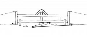
Ellsworth tried splitting the oil flow to the two hydraulic cylinders that folded the booms in, but that wasn’t exact enough. He ended up building a mechanical linkage that the hydraulic cylinders act against in tandem. They link to either end of a central control arm, which pivots at the center of the boom frame. This equalizes the pressure to each side as boom control rods, also connected to the central control arm tips, act against the two boom sections.
Leveling took a little extra thinking, too. Because the boom balances at the center, the weight in each arm has to be equal. Ellsworth hung a soda pop bottle on each end and ran a line from them to a small pvc tank by the operator’s seat. Pumping water from one bottle to the other is enough to balance the boom as needed. It was just one more bit of fine-tuning he discovered that was needed as he went along.
“I started working on it in 1992,” says Ellsworth, who has applied for patents on several aspects of the unique machine. “Sometimes things worked, and sometimes they didn’t. I would eyeball it and think about it, and we might redo it two or three times. By last year, pretty much all the bugs were out of it.”
Contact: FARM SHOW Followup, Mark Ellsworth, Tempe, Arizona.
Click here to download page story appeared in.
Click here to read entire issue
To read the rest of this story, download this issue below or click here to register with your account number.


